
The Marine Assistant Pi Hat Module is the essential brain of your DIY marine system, making everything else work seamlessly. Designed for makers and passionate reefers, this kit requires basic soldering skills to assemble. It offers 10 versatile I/O terminals (6 x 3.3V and 4 x 5V), plus two 12V software-switchable terminals perfect for LED control. Power your custom applications with 3.3V, 5V, and 12V outputs, and unleash your creativity with the integrated mini breadboard for expansion.
If you already have home assistant in your home you can use that but I prefer and advice a separate Pi running HA just for this perpose.
About the Hardware....
The PCB offers exceptional flexibility, with unused GPIO pins conveniently placed near the breadboard. This provides a dedicated area for integrating custom circuitry to suit your needs.
For advanced features and analog sensors, the Sensor Module is required. However, this module serves as the "brain" and is essential for running Home Assistant. None of the other modules will function without it. With this module you can add Binary sensors (Switches, float sensors.....) anything that requres or outputs an on of off signal, there are also 2x 12v switchable supplys for LEDS and a buzzer for alarms.

Piezo buzzer on underside for alarms
i2c output, usefull for the Pi touchscreen
12v input, either via a 3,5mm jack or screw termial
Extra I/O Pins are available here also
Raspberry Pi Gpio header
5v Test Point, used to test and set the voltage safely during setup
The Step down regulator supplys the 5v needed
A custom breadboard, a space foryou to experiment. 5v and 12v rails on each side
2x 12v switchable outputs, ideal for LEDs
3x constant power outputs. 3,3v, 5v and 12v
6x I/O ports with a 3,3v power output, ideal for direct conection to the Raspberry Pi. Float sensors and buttons can also be used here too.
4x I/O ports with 5v power output.

Components
The Kit comes with all the required components, but if you decided to purchace just the PCB then here is a list of what you will need to complete the Pi hat:
The buzzer fits to the bottom of the PCB it has a diameter of 9,5mm and a pin spacing of 6,5mm
- Piezo buzzer.
Size =1,7cm x 2,2cm
- DC/DC Step down regulator
- N channel Mosfet
2x IRFZ24N or similar. (TO-220 package size)
- 3,5mm Power jack
SMD Type, or use Screw terminal
2 port = 6 needed
3 port = 10 needed
4 port = 1 needed
Pin spacing 2,54mm
- Screw terminals
- Resistors
2x 10k Ohm
2x 330 ohm
- Pins and Headers
pins and headers to conect the step down regulator and headers to make the conection to the pi.
Step by Step putting your board together....
What you'll need....
To put your board together you will require some basic soldering skills and a little patience. You will also need the following tools:
-
Soldering Iron and solder (set to 350°c)
-
Wire cutters
-
Tape (For holding in components when turing over)
-
A multimeter for seting the voltage and testing
1. Solder the Terminals
Start by placing all the screw terminals into there coresponding spaces. Along the Bottom are all the 3 pin Terminals, then along the left side and at the top are the 2 pin terminals and finaly at the top left is the 4 pin terminal.
As the terminals are all the same hight you can place a board or piece of cardboard on top to turn it over. Once you have the pins accessable on the underside you can start soldering.
Start by just soldering one leg of each terminal, this way you can turn the PCB over and check the position of everthing. If it all looks good the turn it back over and solder all the pins.
The 12v input terminal is optional, if you plan on using the dc jack then dont put this part in!


2. Power input terminal (DC Jack)
At this point you need to decide how you would like to power the system. You have two options, either via a DC jack or a screw terminal. If you decided to use the screw terminal then continue onto step 3.
The DC Jack is a SMD (Surface mount device) component, meaning it uses solder pads instead of pins. To solder it start by soldering the corner pad on the top right corner, check the allignment and the solder the other three pads. You will notice that the pads on the left are a little tricky to get to due to the terminals but it is doable.


3. Resistors and Mosfets


The resistors and mosfets are used to complete the two 12v switchable outputs. Start with the resistors, they can be inserted either way and will work fine. You can twist the legs to stop them falling out when turning the PCB over to solder. be sure to get the values in the correct position!
The mosfets are the tallest components on the top side of the pcb so they are the final component to be placed, It is important to put them in the correct way. Look at the Markings on the PCB, the Thicker line represents the Back of the Mosfet. The writing on the blackpart of the chip should face the Binary I/O terminals.
Insert them as far as they will go, secure them with a little tape then turn the board over and solder the 6 pins. Cut off any exess Pin wire from the underside with your wirecutters.

4. DC Step down regulator
The step down regulator sits below the Pi header alongside the Reserve I/O and Test points. Insert the 4 (Double) pin headers into the pcb and then place the voltage regulator in the pins. It is important here to have the orientation correct, look at the IN and OUT markings on the PCB and match them up to the Regulator.
Once you have it positioned correctly secure it with a piece of tape, turn the board over and solder the pins. Once the underside is done remove the tape and solder the pins on top.


5. Pi Pin Header
To make the conection to the Raspberry Pi pin headers are needed, unlike all the other components these are placed on the bottom and soldered from the top.
Put them in from the underside and use some tape to secure them in place. Solder one pin at each end then turn the board over and check the Aliignment, If it looks good then you can solder the rest of the pins.
Test fit the Raspberry pi also at this point, you can attach the pi to the Hat with the 11mm spacers and screws provided in the kit.


6. Piezo buzzer
For audiable alarms a piezo buzzer has been selected, it is placed on the under side and is solderd via the two pins on top between the two 12v switchable terminals.
If you purchased the Kit then you will find a small 3d printed spacer for the buzzer, this is to ensure no short circuit can occur if not then position the Piezo buzzer with enough room underneath as to not touch the pins of the 12v switchable terminals.
If you do not wish to have a buzzer then you do not need to solder it in, the hardware will work fine without it.


Finalising and Testing
Well done on completing the soldering, it is now time to do some final inspection to make sure everything has been put in correctly and soldered as it should be. Once you are happy you can continue to set the 5v regulator then it is ready to be paired with a raspberry pi and programmed.
Visual inspection...
Take a good 5 minutes just looking at your soldering joints, do they all look good? Are there any bridges between pins? Are there any "Cold" joints?
Sometimes all it takes is a tiny mistake here to cause you trouble in the future, here are some images of what to look for...


Check for short circuits...
Before even applying power this is a simple test we can do to double check everything is ok. You will need to set your multimeter to continuity, It should make a sound when the two probes touch one another. Check between GND and the 5v outputs on the terminals, also the 3,3v. Test between the + and - of the 3 power output terminals.
Also test between the two 5v pads in the 5v testing area. If there are any conections the multimeter should make a noise, If so go over your soldering again and look for the problem. Once you are happy you can move on to setting the 5v regulator.
Setting the voltage to 5v
Setting the DC/DC step down regulator is an important step to get right as this supplys the Raspberry Pi and its sensors with power.
There are three test points in the test area, the one on its own is a ground point, the middle one is the test point and the outer most one is used to complete the ciruit, these two pads will need to be bridged to complete the circuit.
Step down regulator, turn the Screw to set the voltage.

5v test point on the left, Bridge once set to 5v
GND Test point
-
Conect your 12v power supply, either directly via screw terminals or via a DC wall plug.
-
Touch the black probe to GND and the red one to the test point (Middle pad)
-
Turn the screw in either direction until you get the required 5v
-
disconect the Power source
-
For extra safty secure the Screw on the regulator, hot glue works great for this.
-
Bridge the two 5v pads to complete the circuit.


Congratulations you're all finished
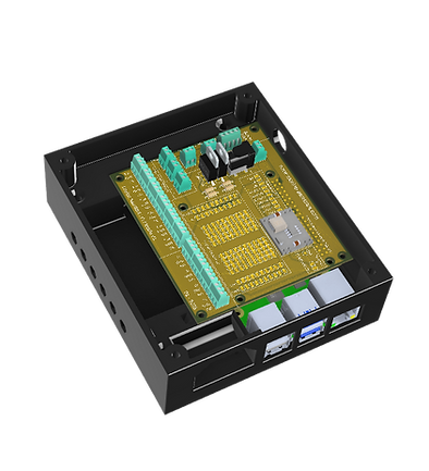
At this point your PCB is finished and ready to go, You can now attach it to your Raspberry Pi and put it in its Case.
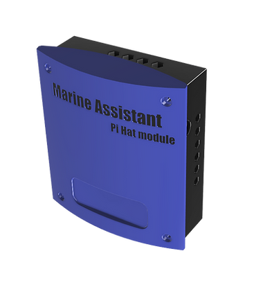
The case is important to protect the electronics from not only humidity around your fishtank but also short circuits. Be sure to put it in a case!

