


%20PCB.png)
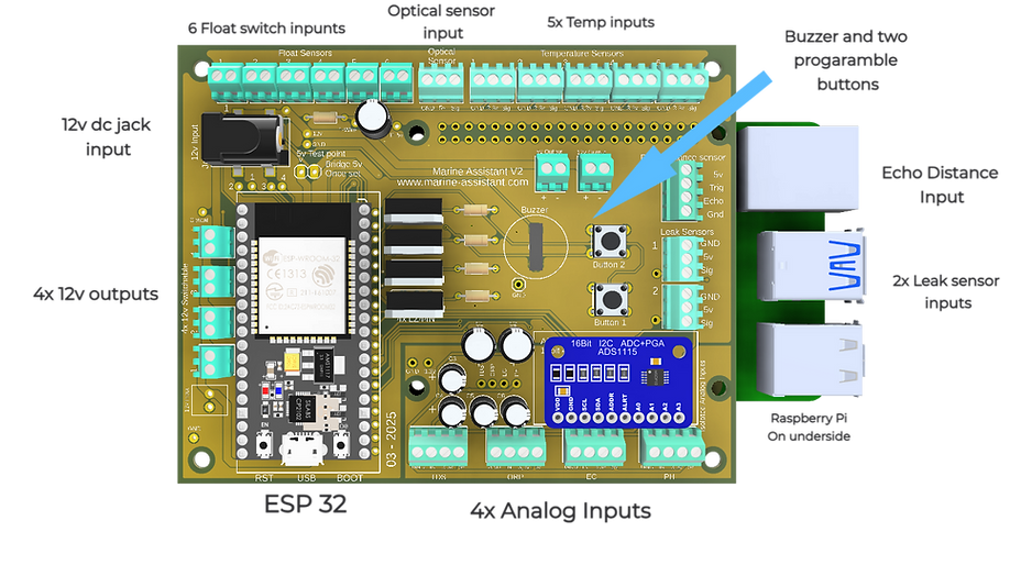
The Main PCB
Marine Assistant is a DIY kit designed for advanced sensor integration, featuring 6 ports for float sensors or switches, 5 temperature sensor ports, an optical water level sensor port, An echo distance sensor ports, and 4 programmable 12V outputs. It also includes 2 leak sensor inputs and 4 analog inputs for advanced sensors like pH, TDS, EC, and ORP, this board uses an ESP32 Node MCU as a data hub and a ADS1115 for the analog data it then sends sensor data via Wi-Fi to the Raspberry Pi.
About the Hardware
The sensor PCB has been designed to be easy to use with a certain "way to use" built in mind, However it is also very flexible on how you use it. For example you could use a Float switch input to add a feed button to automate stopping your pumps and activating a feeder. It also has 4 12v programmable outputs for LEDs or other low current 12v devices, an Echo Sensor port for measuring distance. (Water level in ATO reservoir for example)
This Board also adds 4 analog sensor ports, these are also flexible in how you integrate your sensors. Each port has 5v or 3,3v as a power source, the signal is processed by the onboard ADS1115 ADC chip. These ports are designed to be used with sensors such as PH, TDS, EC, ORP or any other sensor you would like that outputs an analog signal, More details on sensors can be found on the sensor page.
PCB%20TOP_edited_pn.png)
Components
The Kit comes with all the required components, but if you decided to purchase just the PCB then here is a list of what you will need to complete the Pi hat:
The buzzer fits to the bottom of the PCB it has a diameter of 9,5mm and a pin spacing of 6,5mm
- Piezo buzzer.
Size =1,7cm x 2,2cm
- DC/DC Step down regulator
- Resistors
4x 10k Ohm
4x 330 ohm
1x 4,7K ohm
- 3,5mm Power jack
SMD Type, or use Screw terminal
Espressif ESP32 and ESP32-WROOM 32 are also compatible.
- ESP32 NodeMCU
- N channel Mosfet
4x LZ44 or similar. (TO-220 package size)
2 port = 12 needed
3 port = 8 needed
4 port = 5 needed
Pin spacing 2,54mm
- Screw terminals
- Pins and Headers
pins and headers to conect the step down regulator and headers to make the conection to the pi.

Step by Step Guide
What you'll need....
To put your board together you will require some basic soldering skills and a little patience. Many of these steps are the same as the Pi Hat module so it should all be familiar. You will need the following tools:
-
Soldering Iron and solder (set to 350°c)
-
Wire cutters
-
Tape (For holding in components when turing over)
-
A multimeter for seting the voltage and testing
Important information:
The images below are all of the V1 hardware, they will be changed out over time once I am able to retake the pictures. The guide is still valid and all text hav been updated for the V2 ov the hardware.
1. Power input terminal (DC Jack)
At this point you need to decide how you would like to power the system. You have two options, either via a DC jack or a screw terminal. If you decided to use the screw terminal then continue onto step 3.
The DC Jack is a SMD (Surface mount device) component, meaning it uses solder pads instead of pins. To solder it start by wetting the pads with solder then removing as much as possible with either a solder sucker or wick. Place the jack over the pads and start by soldering a corner pad, check the allignment and the solder the other three pads. Apply pressure down and slowly add heat to each pad until the jack fits flat on the PCB.


2. Solder the Terminals
Start by placing all the screw terminals into there corresponding spaces. Place the terminals in their corresponding slot based on the PCB markings.
As the terminals are all the same hight you can place a board or piece of cardboard on top to turn it over. Once you have the pins accessible on the underside you can start soldering.
Start by just soldering one leg of each terminal, this way you can turn the PCB over and check the position of everything. If it all looks good the turn it back over and solder all the pins.
The 12v input terminal is optional, if you plan on using the dc jack then don't put this part in!


3. Resistors, Caps and Mosfets
The resistors and mosfets are used to complete the 12v switchable outputs. Start with the resistors, they can be inserted either way and will work fine. You can twist the legs to stop them falling out when turning the PCB over to solder. be sure to get the values in the correct position!
The mosfets are the tallest components on the top side of the pcb so they are the final component to be placed, It is important to put them in the correct way. Look at the Markings on the PCB, the Thicker line represents the Back of the Mosfet. The writing on the blackpart of the chip should face the reserve I/O screw terminals.
Insert them as far as they will go, secure them with a little tape then turn the board over and solder pins. Cut off any exess Pin wire from the underside with your wirecutters.
There are at various points on the board Capacitiors, these are used for filtering the power lines, there are two types 100uf and 0,1uf. place themaccordingly and solder fromthe underside.


4. DC Step down regulator
The step down regulator sits below the ESP32 along with the resistors. Insert the 4 (Double) pin headers into the pcb and then place the voltage regulator in the pins. It is important here to have the orientation correct, look at the IN and OUT markings on the PCB and match them up to the Regulator.
Once you have it positioned correctly secure it with a piece of tape, turn the board over and solder the pins. Once the underside is done remove the tape and solder the pins on top.


5. Analog chip (ADS1115)
The ADS1115 Chip sits on its own fixed soldered pin header, meaning it cant be removed like the Pi of ESP 32. This is to ensure a better conection and better data.
Solder the small pin header to the sensor module first and ensure it is straght, then place the ADS1115 on top and solder a single pin, check alignment then solder the rest.
6. Pin Headers
The ESP32 and raspberry pi are mounted on pin header sockets, this ensures it is replacable and gives access to the components below.
Insert the header sockets from the top and secure with tape. Solder one pin at each end of the Sockets and then check alignment. If all is good then you can solder the rest of the header socket pins.
Do this on the top side for the ESP32 and on the bottom for the Raspberry Pi.


The best way to check alignment is to insert the Components themselves into the headers.
7. Piezo buzzer and buttons
For audiable alarms a piezo buzzer has been selected, it is placed on the under side and is solderd via the two pins on top underneath the ESP32.
If you do not wish to have a buzzer then you do not need to solder it in, the hardware will work fine without it.
Next to the buzzer are two spaces for Buttons, push them intoplace and solder from the underside

Finalising and Testing
Well done on completing the soldering, it is now time to do some final inspection to make sure everything has been put in correctly and soldered as it should be. Once you are happy you can continue to set the 5v regulator then it is ready to be programmed and set-up.
Visual inspection...
Take a good 5 minutes just looking at your soldering joints, do they all look good? Are there any bridges between pins? Are there any "Cold" joints?
Sometimes all it takes is a tiny mistake here to cause you trouble in the future, here are some images of what to look for...


Check for short circuits...
Before even applying power this is a simple test we can do to double check everything is ok. You will need to set your multimeter to continuity, It should make a sound when the two probes touch one another. Check between GND and the 5v outputs on the terminals, also the 3,3v. Test between the + and - of the power output terminals.
Also test between the two 5v pads in the 5v testing area. If there are any connections the multimeter should make a noise, If so go over your soldering again and look for the problem. Once you are happy you can move on to setting the 5v regulator.
Setting the voltage to 5v
Setting the DC/DC step down regulator is an important step to get right as this supplies the ESP32 and its sensors with power.
There are three test points in the test area, the two smaller ones are labelled 12v and GND respectively, these can be used to assure your power supply is outputting 12v. The two larger pads are is the test point and the outer most one is used to complete the circuit, these two pads will need to be bridged to complete the circuit. Left to test, Right to complete the circuit.
5vajust_edited_pn.png)
5vtest_edited.png)
-
Conect your 12v power supply, either directly via screw terminals or via a DC wall plug.
-
Touch the black probe to GND and the red one to the 12v test point, if all is ok then place probe on th eleft 5v test pad.
-
Turn the screw in either direction until you get the required 5v
-
Disconect the Power source
-
For extra safty secure the Screw on the regulator, hot glue works great for this.
-
Bridge the two 5v pads to complete the circuit.

Congratulations you're all finished
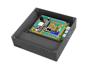
At this point your PCB is finished and ready to go, You can now put it in its case and place the ESP32 in its socket.
The case is important to protect the electronics from not only humidity around your fishtank but also short circuits. Be sure to put it in a case! In the case for the sensor module there are also 5 bays for the Analog sensors you wish to add and other features too...
Click here for more info on the 3D Printed Case
.png)
CASE.png)


